CCNA Overview and Packet Life
A general CCNA cheat sheet followed by the complete visual encapsulation and packet-life explanation.
CCNA 200-301 v1.1 exam map
The percentages and domain names come from Cisco's official 200-301 CCNA v1.1 exam topics.
General CCNA rules to remember
- A host uses its subnet mask or prefix length to decide whether a destination is local or remote.
- For a remote destination, the host sends the first frame to the default gateway MAC address.
- A Layer 2 switch forwards frames by destination MAC address and VLAN.
- A router forwards packets by destination IP address using longest-prefix match.
- A router removes the incoming Layer 2 header and creates a new Layer 2 header for the next link.
- Normal routing preserves source and destination IP addresses, but decreases TTL or Hop Limit.
- NAT can change IP addresses. PAT can also change TCP or UDP port numbers.
- ARP maps a local IPv4 next-hop address to a MAC address. IPv6 uses Neighbor Discovery.
- VLANs create separate Layer 2 broadcast domains.
- An access port normally carries one untagged data VLAN. A trunk carries multiple VLANs with 802.1Q tags.
- The native VLAN is normally untagged on an 802.1Q trunk. Both ends must agree.
- STP blocks redundant Layer 2 paths to prevent loops. EtherChannel makes multiple links act as one logical link.
- Routing chooses longest prefix first, then administrative distance, then the protocol metric.
- ACLs process top to bottom, stop at the first match, and end with an implicit deny.
- Inbound and outbound ACL direction is relative to the interface, not the user or server.
- An SVI usually needs the VLAN to exist and at least one active Layer 2 member or trunk path.
up/upnormally means Layer 1 and Layer 2 are operational.administratively downmeansshutdown.- Do not save a remote change until you verify management access, forwarding, and required services.
IPv4 and IPv6 quick reference
Important IPv4 ranges
| Range | Purpose |
|---|---|
10.0.0.0/8 | Private IPv4 |
172.16.0.0/12 | Private IPv4 |
192.168.0.0/16 | Private IPv4 |
169.254.0.0/16 | IPv4 link-local, often called APIPA on Windows |
127.0.0.0/8 | Loopback |
224.0.0.0/4 | IPv4 multicast |
0.0.0.0/0 | Default route |
255.255.255.255 | Limited broadcast |
Important IPv6 ranges
| Range | Purpose |
|---|---|
2000::/3 | Global unicast |
FC00::/7 | Unique local |
FE80::/10 | Link-local |
FF00::/8 | Multicast |
::1/128 | Loopback |
::/128 | Unspecified address |
::/0 | Default route |
| No broadcast | IPv6 uses multicast instead |
Subnet size table
| Prefix | Subnet mask | Addresses | Traditional usable hosts | Block size in changing octet |
|---|---|---|---|---|
| /24 | 255.255.255.0 | 256 | 254 | 1 in third octet |
| /25 | 255.255.255.128 | 128 | 126 | 128 |
| /26 | 255.255.255.192 | 64 | 62 | 64 |
| /27 | 255.255.255.224 | 32 | 30 | 32 |
| /28 | 255.255.255.240 | 16 | 14 | 16 |
| /29 | 255.255.255.248 | 8 | 6 | 8 |
| /30 | 255.255.255.252 | 4 | 2 | 4 |
| /31 | 255.255.255.254 | 2 | 2 on supported point-to-point links | 2 |
| /32 | 255.255.255.255 | 1 | One host route | 1 |
Fast subnet method: Find the first mask octet that is not 255 or 0. Calculate 256 - mask octet. The result is the subnet increment.
Wildcard masks
| Subnet mask | Wildcard | Typical use |
|---|---|---|
| 255.255.255.255 | 0.0.0.0 | Exact host |
| 255.255.255.252 | 0.0.0.3 | /30 |
| 255.255.255.248 | 0.0.0.7 | /29 |
| 255.255.255.240 | 0.0.0.15 | /28 |
| 255.255.255.224 | 0.0.0.31 | /27 |
| 255.255.255.192 | 0.0.0.63 | /26 |
| 255.255.255.128 | 0.0.0.127 | /25 |
| 255.255.255.0 | 0.0.0.255 | /24 |
| 255.255.0.0 | 0.0.255.255 | /16 |
| 255.0.0.0 | 0.255.255.255 | /8 |
Switching and routing cheat sheet
How a switch handles a frame
- Learn the source MAC on the incoming port and VLAN.
- Look up the destination MAC in the same VLAN.
- Forward a known unicast to one port.
- Flood unknown unicast, broadcast, and relevant multicast within the VLAN.
- Do not send the frame back out the port where it arrived.
How a router chooses a route
- Use the most specific matching prefix.
- If sources advertise the same prefix, prefer the lowest administrative distance.
- If the same routing protocol has multiple paths, prefer the best metric.
- Install eligible equal-cost paths when supported.
Rapid PVST+ election logic
- Lowest bridge ID becomes root. Bridge ID includes priority and MAC.
- Each non-root switch chooses one root port with the best path to root.
- Each segment chooses one designated port.
- Other redundant ports become alternate and discard traffic.
- Use PortFast only on true edge ports. Use BPDU Guard to protect them.
EtherChannel mode pairs
| Protocol | Working combinations |
|---|---|
| LACP | active-active or active-passive |
| PAgP | desirable-desirable or desirable-auto |
| Static | on-on only |
Member links must match important Layer 2 or Layer 3 settings.
Common administrative distances
| Route source | Default AD |
|---|---|
| Connected | 0 |
| Static | 1 |
| eBGP | 20 |
| Internal EIGRP | 90 |
| OSPF | 110 |
| RIP | 120 |
| External EIGRP | 170 |
| iBGP | 200 |
Administrative distance compares routes to the same prefix from different route sources. It is not carried end to end as part of the IP packet.
Common ports, protocol numbers, and services
| Service | Transport and port | Remember |
|---|---|---|
| FTP control/data | TCP 21 / TCP 20 | Legacy file transfer. Separate control and data behavior. |
| SSH | TCP 22 | Encrypted remote CLI and SCP transport. |
| Telnet | TCP 23 | Unencrypted. Know it, but do not use for normal management. |
| SMTP | TCP 25 | Mail transfer between servers. |
| DNS | UDP 53 and TCP 53 | UDP is common for queries. TCP supports large responses and zone transfers. |
| DHCP | UDP 67 server / UDP 68 client | DORA: Discover, Offer, Request, Acknowledge. |
| HTTP | TCP 80 | Unencrypted web traffic. |
| HTTPS | TCP 443 | HTTP protected by TLS. |
| TFTP | UDP 69 | Simple and unencrypted file transfer. |
| NTP | UDP 123 | Time synchronization. |
| SNMP polling | UDP 161 | Management queries. |
| SNMP traps | UDP 162 | Unsolicited notifications. |
| Syslog | UDP 514 commonly | Central event logging. Other secure transports can also be used. |
| RADIUS | UDP 1812 / 1813 | Authentication/authorization and accounting. |
| IP protocol number | Protocol |
|---|---|
| 1 | ICMP for IPv4 |
| 6 | TCP |
| 17 | UDP |
| 47 | GRE |
| 50 | IPsec ESP |
| 51 | IPsec AH |
| 58 | ICMPv6 |
| 89 | OSPF |
TCP versus UDP
| TCP | UDP |
|---|---|
| Connection-oriented | Connectionless |
| Sequence numbers and acknowledgments | No built-in delivery acknowledgment |
| Retransmits missing data | No built-in retransmission |
| Ordered byte stream | Message-oriented datagrams |
| Larger header and more state | 8-byte header and low overhead |
| Used when reliable ordered delivery matters | Used for speed, simplicity, multicast, or application-managed recovery |
Security and network services reminders
ACL logic
- Standard ACLs match source IPv4 address.
- Extended ACLs can match protocol, source, destination, and ports.
- Place extended ACLs near the source when practical.
- Place standard ACLs near the destination when practical.
- Verify both placement and direction.
Layer 2 security
- Port security limits source MAC addresses on an access port.
- DHCP snooping blocks untrusted DHCP server messages and builds bindings.
- Dynamic ARP Inspection validates ARP using trusted bindings or ARP ACLs.
- IP Source Guard restricts source IP and MAC combinations on access ports.
QoS process
- Classify traffic.
- Mark traffic, often with DSCP.
- Queue during congestion.
- Police by dropping or remarking above a rate.
- Shape by buffering to smooth traffic to a rate.
AAA
- Authentication: Who are you?
- Authorization: What may you do?
- Accounting: What did you do and when?
- TACACS+ and RADIUS centralize access control.
Automation and programmability quick sheet
REST concepts
| HTTP verb | Typical CRUD action |
|---|---|
| GET | Read |
| POST | Create or invoke |
| PUT | Replace |
| PATCH | Partially update |
| DELETE | Delete |
JSON structure
{
  "hostname": "SW1",
  "vlans": [10, 20, 30],
  "enabled": true,
  "management_ip": null
}
Object uses braces. Array uses brackets. Strings use quotes. Values can be strings, numbers, booleans, null, arrays, or objects.
Controller-based networking
- The data plane forwards traffic.
- The control plane builds forwarding decisions.
- The management plane configures and observes the device.
- Northbound APIs connect controllers to applications.
- Southbound APIs connect controllers to infrastructure.
Configuration management
- Ansible commonly uses declarative playbooks and does not require a permanent agent on Cisco devices.
- Terraform manages desired infrastructure state through providers.
- Idempotent automation produces the same intended state when run repeatedly.
- Validate and preview changes before production deployment.
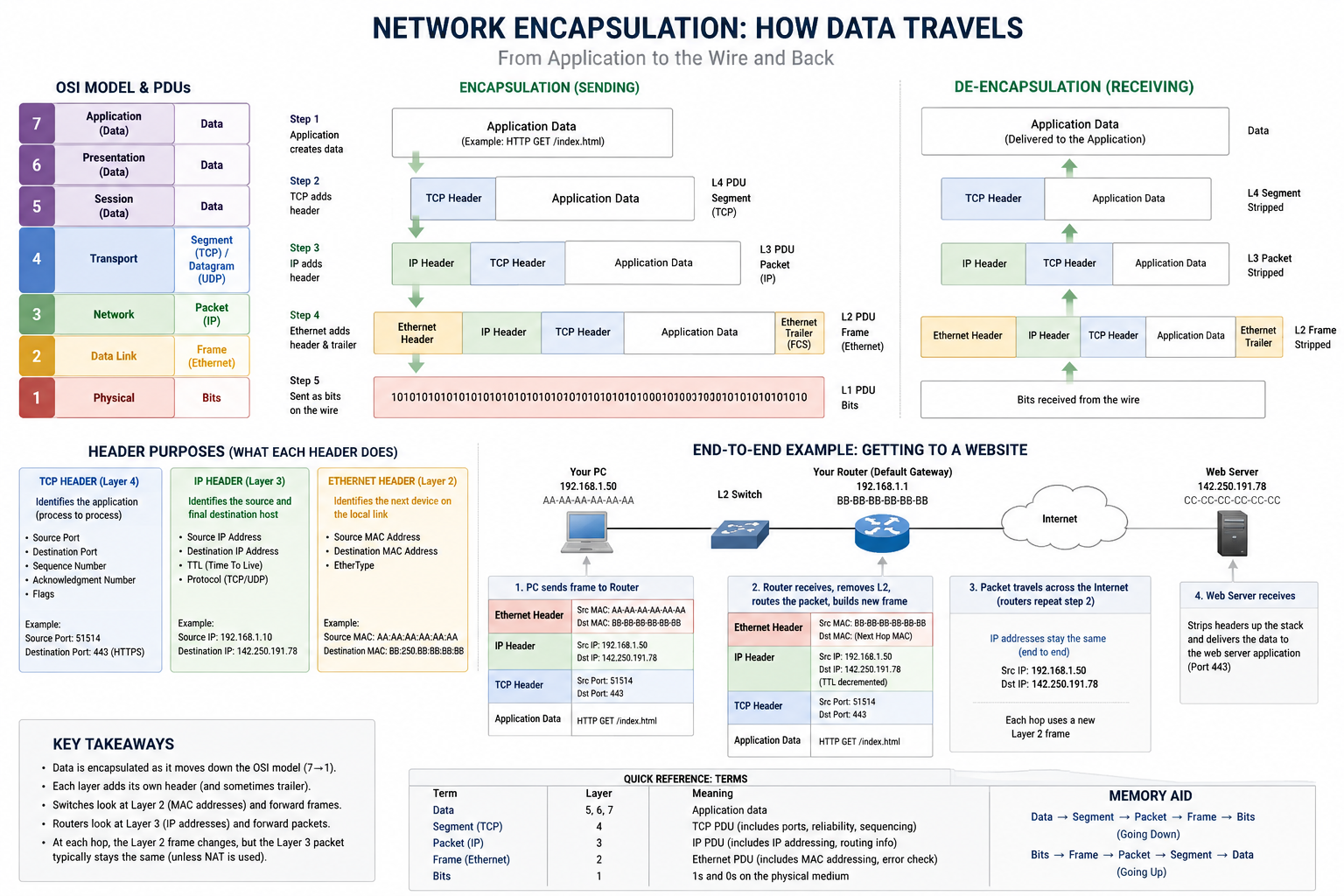
Packet life and encapsulation
The rest of this page preserves the full visual explanation from the previous edition and expands the path from application data to bits.
Encapsulation and de-encapsulation map
OSI model and PDU names
| 7 | Application Network service used by the application | Data |
| 6 | Presentation Encoding, encryption, compression | Data |
| 5 | Session Conversation control | Data |
| 4 | Transport Process-to-process delivery | TCP segment UDP datagram |
| 3 | Network Host-to-host routing | IP packet |
| 2 | Data Link Local-link delivery | Ethernet frame |
| 1 | Physical Signals and media | Bits |
Layers 5 through 7 are usually treated as one Application layer in the TCP/IP model. They do not always appear as three separate headers in a packet capture.
Encapsulation: sending down the stack
Application creates data
Example: HTTP GET /index.html
TCP or UDP adds a header
IP adds a header
Ethernet adds header and trailer
NIC sends signals
De-encapsulation: receiving up the stack
NIC receives signals
Ethernet validates and removes Layer 2
IP removes Layer 3
TCP or UDP delivers by port
Application receives data
Going up: Bits → Frame → Packet → Segment or Datagram → Data
What each header does
TCP header: Layer 4
Job: Identify the sending and receiving processes and provide reliable, ordered delivery.
- Source port
- Destination port
- Sequence number
- Acknowledgment number
- Flags
- Window size
- Checksum
Example: 51514 → 443
IP header: Layer 3
Job: Identify the original source host and final destination host across routed networks.
- Source IP
- Destination IP
- TTL or Hop Limit
- Protocol or Next Header
- Length and fragmentation fields
Example: 192.168.10.50 → 142.250.191.78
Ethernet header and trailer: Layer 2
Job: Deliver the packet across the current Ethernet link or VLAN.
- Source MAC
- Destination MAC
- EtherType
- Optional 802.1Q VLAN tag
- FCS trailer
Example: PC MAC → default-gateway MAC
End-to-end example: PC opens an HTTPS website
192.168.10.50
AA-AA-AA-AA-AA-AA
Forwards frames
Uses MAC table + VLAN
192.168.10.1
BB-BB-BB-BB-BB-BB
Route packets
New Layer 2 wrapper per link
142.250.191.78
TCP 443
1. PC decides local or remote
The PC applies its subnet mask. The website is outside 192.168.10.0/24, so the next hop is the default gateway.
The PC uses ARP to learn the gateway MAC address.
2. PC sends the first frame
| Layer 2 | Src MAC: PC Dst MAC: gateway |
|---|---|
| Layer 3 | Src IP: PC Dst IP: web server |
| Layer 4 | Src port: ephemeral Dst port: 443 |
3. Switch forwards the frame
The switch learns the source MAC on the incoming port and VLAN. It looks up the destination MAC and forwards the frame.
A basic Layer 2 switch does not route by the destination IP address.
4. Router removes and rebuilds Layer 2
The router removes the Ethernet header and FCS, decrements TTL, performs a longest-prefix route lookup, then builds a new frame for the next hop.
5. What normally stays the same
Source IP, destination IP, TCP source port, and TCP destination port remain end to end.
Exceptions: NAT or PAT can change IP addresses and ports.
6. Server receives and unwraps
The server removes Layer 2, then Layer 3, then Layer 4. TCP destination port 443 delivers the data to the HTTPS service.
For HTTPS, the HTTP request is encrypted inside TLS.
| Field | Across a Layer 2 switch | Across a router | NAT/PAT exception |
|---|---|---|---|
| Source MAC | Normally unchanged | Replaced with router exit-interface MAC | Not the NAT function |
| Destination MAC | Normally unchanged | Replaced with next-hop MAC | Not the NAT function |
| Source IP | Unchanged | Normally unchanged | Can be translated |
| Destination IP | Unchanged | Normally unchanged | Can be translated by destination NAT |
| TTL / Hop Limit | Unchanged | Decreased by one | Still decreased by routing |
| TCP/UDP ports | Unchanged | Normally unchanged | PAT can translate a port |
Expanded CCNA explanation
Packet versus frame
| Question | IP packet | Ethernet frame |
|---|---|---|
| Layer | Layer 3 | Layer 2 |
| Main addresses | Source and destination IP | Source and destination MAC |
| Scope | Travels through routed networks | Crosses one local Ethernet segment or VLAN |
| Device lookup | Router uses destination IP and longest-prefix match | Switch uses destination MAC and VLAN |
| At a routed hop | Forwarded after TTL/Hop Limit processing | Old frame removed and a new frame built |
How the host chooses the destination MAC
- The host compares the destination IP with its own subnet using the subnet mask.
- For a local destination, the host resolves the final host MAC.
- For a remote destination, the host resolves the default gateway MAC.
- ARP resolves IPv4 next hops. IPv6 Neighbor Discovery resolves IPv6 next hops.
What a router does in order
- Receives and validates the incoming Layer 2 frame.
- Removes the incoming Layer 2 header and trailer.
- Reads the destination IP address.
- Decrements TTL or Hop Limit.
- Performs a longest-prefix route lookup.
- Applies configured policy, such as ACL, NAT, QoS, or firewall inspection.
- Resolves the next-hop Layer 2 address when required.
- Builds a new Layer 2 frame for the outgoing link.
Ethernet, IPv4, TCP, and UDP header quick reference
| Header | Common size | Important fields | Key fact |
|---|---|---|---|
| Ethernet II | 14-byte header + 4-byte FCS Optional 4-byte VLAN tag | Destination MAC, source MAC, EtherType, optional VLAN tag, FCS | Used for the current Ethernet link. MAC addresses change at routed hops. |
| IPv4 | 20 bytes minimum | Source IP, destination IP, TTL, protocol, header checksum, fragmentation | Routers decrement TTL and recalculate the IPv4 header checksum. |
| IPv6 | 40-byte base header | Source, destination, Hop Limit, Next Header, Traffic Class, Flow Label | No base-header checksum. Routers do not fragment IPv6 packets. |
| TCP | 20 bytes minimum | Ports, sequence, acknowledgment, flags, window, checksum, options | Reliable ordered byte stream. |
| UDP | 8 bytes | Source port, destination port, length, checksum | No connection setup, sequencing, or retransmission. |
MTU and MSS
- Common Ethernet MTU: 1500-byte Layer 3 packet.
- Common IPv4 TCP MSS without options: 1460 bytes, because 1500 - 20 IPv4 - 20 TCP.
- Common IPv6 TCP MSS without options: 1440 bytes, because 1500 - 40 IPv6 - 20 TCP.
- VPN, PPPoE, and tunneling headers reduce available payload size.
What Wireshark might not show
- The Ethernet preamble and interframe gap are normally not captured.
- The NIC often removes the Ethernet FCS before the operating system receives the frame.
- Checksum and segmentation offload can make host-side captures look unusual.
- A normal switched port does not receive unrelated unicast frames. Use SPAN, a TAP, or an endpoint capture.
Common mistakes to avoid
| Incorrect idea | Correct model |
|---|---|
| A router adds an Ethernet header and the data becomes a packet. | The IP packet already exists. Ethernet wraps the packet to create a frame. |
| The destination MAC is the remote web server MAC. | For a remote network, the first destination MAC is the default gateway MAC. |
| A switch forwards by destination IP. | A basic Layer 2 switch forwards by destination MAC and VLAN. |
| MAC addresses remain end to end. | MAC addresses normally change at every routed hop. |
| IP addresses always remain end to end. | They normally do, but NAT can translate them. |
| ARP finds a MAC address anywhere on the Internet. | ARP resolves only an IPv4 address on the local link. |
| Port 443 is a physical switchport. | TCP port 443 identifies an application socket for HTTPS. |
Key takeaways
- Layer 4 adds process identifiers. Layer 3 adds end-to-end logical addressing. Layer 2 adds local-link addressing.
- Switches forward frames. Routers forward packets.
- A router creates a new Layer 2 frame for each routed link.
- The destination IP drives routing. The next-hop MAC drives local Ethernet delivery.
- The PDU name depends on the layer being discussed.
Show the original reference diagram